Here's some more gen on this module. If faulty, there should not be difficult to replace any faulty component, there's nothing exotic in there.
Here's the PCB inside:

- Coolant level PCB, component side.jpg (125.94 KiB) Viewed 15472 times
and this is my tracing of the circuitry:

- Coolant level circuitry.jpg (90.64 KiB) Viewed 15472 times
As far as I can work out, the basic operation of the circuit is as follows:
When the coolant level switch in the radiator is closed, the string of transistors; Q3, Q4, Q5, Q6 and Q7 are switched off, so no current flows through Q7 and the 1.4w lamp in the instrument cluster will be off.
When the coolant level drops, the switch goes open and Q1/Q2 provide a square wave voltage output (at collector of Q2, R4, R5) which slowly charges C4, switching on Q3/Q4, this slowly charges the large C6 capacitor (220 microfarads) and this then switches on Q5/Q6 and then Q7.
The charging of the capacitors delays the switching of Q7 for bout 12 seconds, so avoiding the coolant warning lamp from illuminating if the coolant is sloshing around, or forced to one side whilst cornering.
The diode, centre right of the diagram had me puzzled for a moment, then I realised that it is there to provide a lamp test function when the ignition is switched on, via the “Reg.L” connector.
I thought it worth recording this on here for posterity, as I couldn't find out much about this module on a quick internet search.
The "measure" pin on the connector (that's what is screen printed on the PCB) isn't connected, so it may provide a test point when the boards are checked by the manufacturer.
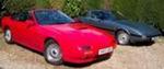
KIMI 1 : 1st Gen, "hybrid" 1983 silver S2 running gear in a 1985 S3 shell, SORN'd, long term resto project
KIMI 2 : 1st Gen, 1983 silver S2 - now sold to Ian Mothersole on here.
KIMI 3 : 1st Gen, 1983 red S3
Plus a 2004 Full Bridgeported RX-8